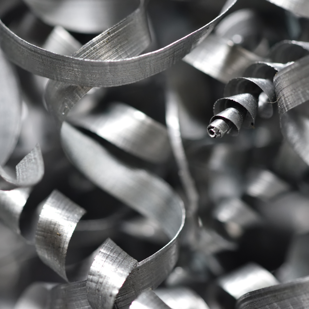



Stainless steel is highly ductile and work-hardens easily. Because the metal stretches and hardens as you cut it, light feeds and rubbing tools frequently cause chips to come off in long, stringy ribbons. Managing these chips requires the right insert geometry, proper cutting parameters, and smart tool selection.
Breaking chips during general turning comes down to using the right insert geometry, maintaining enough feed, and cutting deeply enough for the chipbreaker to function.
What Works Best
- Use a stainless-specific insert: Always choose an insert with a real chipbreaker rather than a flat-top or “general purpose” geometry.
- Increase the feed rate: A higher feed rate makes the chip thick enough to curl and snap instead of forming a continuous ribbon.
- Avoid shallow, rubbing cuts: Stainless steel behaves much better when the tool is actively cutting rather than polishing the surface.
- Maintain enough depth of cut (DOC): Shallow cuts often make chip control worse because they do not allow the chip breaker to engage.
Tooling and Parameter Choices
For common grades like 304 and 316 stainless, a sharp, positive-rake insert with a tight chip groove provides the most help. If you are working with tougher stainless steel or duplex grades, you need a more aggressive chip breaker. In some setups, a dedicated stainless insert is the only thing standing between manageable chips and a messy “bird’s nest.” Machinists also sometimes add a small land or a slight edge modification to force the chip to fold and break.
When adjusting your machine, try a thicker chip before you try increasing the speed. Pushing the feed rate stiffens the chip, which forces it to curl and fracture against the breaker. Increasing the depth of cut can also improve chip control if your insert allows it. Higher feed helps chip breakage more reliably than just pushing your RPM.
A Practical Step-by-Step Approach
- Start with a stainless-rated insert, an aggressive feed, and a depth of cut that fully engages the chip breaker.
- If the chips remain long and stringy, increase the feed rate first.
- If that does not work, adjust your depth of cut next.
- Only experiment with spindle speed after adjusting feed and depth of cut.
- For long-run production, use high-pressure coolant or a directed coolant stream to clear away the chips once they begin breaking.
How to Break Chips During Threading
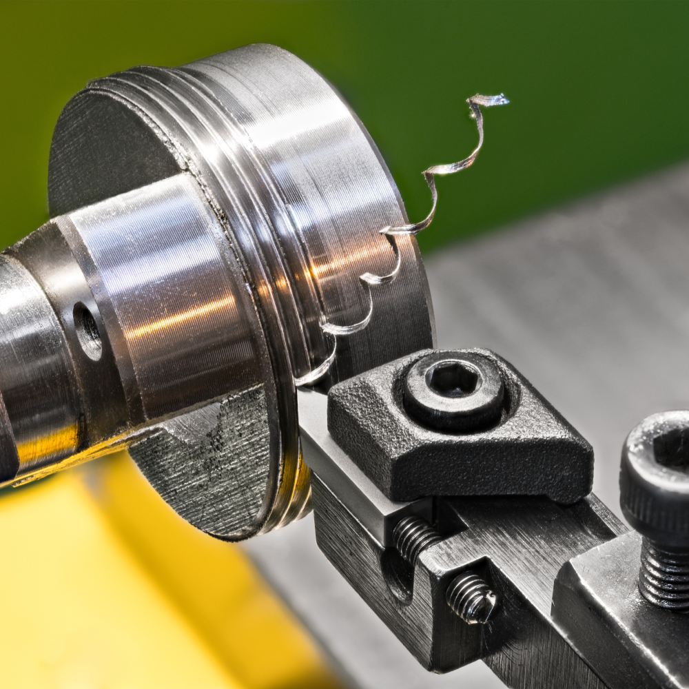
On a standard lathe, chip control during threading is limited because the feed rate is locked to the thread pitch. Because you cannot change the feed rate to fix chip thickness, you must rely on geometry, pass strategy, and coolant.
Core Threading Strategies
- Pick a chip-control insert: Use a thread insert designed for chip control rather than one that only forms the thread shape. These specialized geometries generate shorter chips in difficult metals.
- Use modified flank infeed: When your machine control and thread form allow it, prefer a modified flank infeed over a simple, straight radial infeed for conventional external or internal thread turning. Modified flank infeed generally delivers superior chip control. Chip-breaking thread geometries should not be used with radial infeed.
- Increase the number of passes: Use more passes combined with a lighter last pass instead of forcing one heavy cut. This protects the tool nose and keeps the cuts manageable.
- Apply heavy coolant: Use plenty of coolant to wash chips away and prevent packing. Directed or through-tool coolant is ideal.
Advanced Machine Functions
If your machine supports oscillation threading (sometimes referred to as Opti-threading), it is the cleanest solution available. This function introduces an interrupted cut into the threading cycle by varying the tool path during passes. It breaks the chips into short segments without harming the quality of the thread. This is a specialized control feature and depends entirely on your machine’s capabilities.
Working on Standard Lathes
If your lathe does not have an oscillation function, you cannot fix chip control by changing the feed. Instead, rely on optimized insert geometry, a modified infeed strategy, sufficient coolant, and a program that avoids dwelling or rubbing. For stubborn or gummy stainless steels, it may be better to rough out the profile with a turning tool first, leaving only a light finishing pass for the threading tool.
Practical Threading Setup Guide
To set up for stainless steel threading, start with:
- A sharp, positive thread insert with built-in chipbreaker geometry.
- A modified flank infeed path (if supported by your control).
- Enough individual passes to keep cutting forces manageable.
- High-pressure or well-aimed coolant streams.
- A small finishing allowance to ensure the final pass is light and clean.
Caution on Rubbing: If your threading cut is too light, the insert will rub instead of cutting. Rubbing ruins chip control and work-hardens stainless steel. If this happens, a slightly deeper effective cut or a different insert geometry helps far more than slowing down your spindle.
How to Choose the Right Chip breaker for Threading Stainless Steel
The ideal chip breaker for threading stainless steel is a sharp, stainless-specific thread insert geometry. It must have enough chip-forming ability to curl the chip without rubbing. The geometry needs to be aggressive enough to handle stainless steel, but not so heavy that it spikes cutting forces and triggers chatter.
Key Selection Factors
- Prioritize sharpness: Pick a sharp geometry first to handle sticky, work-hardening stainless steels.
- Stay in a real cutting regime: Only use chip-breaking geometries when the depth of cut is heavy enough to load the insert. If the cut is too light, the chip breaker will not force the chip to curl and fracture.
- Look for ISO M recommendations: Choose inserts specifically recommended for ISO M stainless steel, as these are designed for long-chip control.
- Avoid over-honed edges: An over-honed, rounded edge will rub against the metal, causing the stainless steel to gall or work-harden.
Insert Styles and Selection Rules
For single-point thread turning, starting with a sharp insert that features a polished chipformer is the safest choice. If you need tighter chip control, transition to a chip-breaking thread insert, but only if your depth of cut and infeed method allow it to function properly.
Threading Scenario |
Best Choice / Strategy |
|
External Threading |
Start with a sharp geometry; step up to a chip-breaking geometry if chips remain too long. |
|
Internal Threading |
Favor the sharpest geometry that provides acceptable chip control due to tighter clearances and forces. |
| Very Small Parts |
Use sharp-edged inserts with chipbreakers to minimize cutting forces and vibration. |
| Intermittent / Poor Evacuation |
Prioritize chip control and coolant over maximum insert strength. |
A Simple Rule of Thumb
If the stainless steel is gummy and the thread cut is light, select a sharp insert with a conservative chipbreaker. If the thread cut is heavy enough to fully load the insert, an active chip-breaking geometry will control the chips much better. For 304 and 316 grades, this combined approach works far better than using a generic thread insert.
Have questions? We have answers. Reach out to our team or explore our blog to learn more.