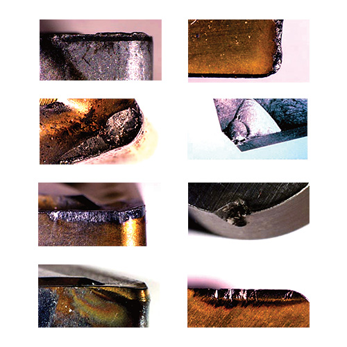
The 8 Insert Failure Modes
Insert Failure Modes at a Glance
| Failure mode | What you see | Main cause | Common fix |
|
Flank wear
|
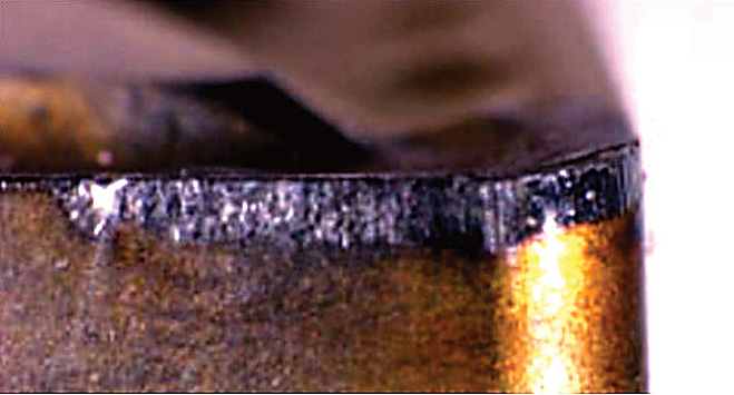
Even wear band on the flank face below the cutting edge | Cutting speed too high, or grade not wear resistant enough | Lower speed, use a harder coated grade |
|
Crater wear
|
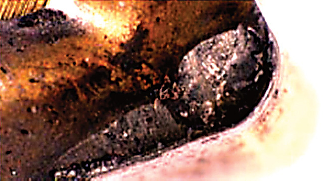
Concave dip on the rake face behind the cutting edge | High heat where the chip meets the tool | Lower speed or feed, use a coated grade with an Al2O3 layer |
|
Built-up edge (BUE)
|
Workpiece material welded to the cutting edge | Cutting speed too low on gummy material | Raise speed, use a sharp PVD-coated grade |
|
Chipping
|
Small, irregular breaks along the cutting edge | Interrupted cut, vibration, hard scale, weak edge | Use a tougher grade and a stronger edge prep |
|
Thermal (comb) cracks
|
Fine cracks across the cutting edge, like a comb | Big swings in temperature | Use a tougher grade, keep coolant steady or run dry |
|
Plastic deformation
|
Edge that looks slumped, rolled over, or pressed in | Heat and pressure beyond the grade’s hot hardness | Lower speed and feed, use a grade with better hot hardness |
|
Notch wear
|
Notch at the depth of cut line or trailing edge | Work-hardened skin, scale, or oxidation | Vary the depth each pass, increase the lead angle |
|
Edge fracture
|
Large piece broken from the edge or nose radius | Shock load, chatter, chip jamming, hard inclusion, or brittle grade | Use a tougher grade, reduce feed and depth |
What Is Flank Wear?
- Reduce cutting speed.
- Step up to a harder coated grade or pick a more wear-resistant grade.
- Check that coolant reaches the cutting edge.
- For work hardening materials, select a smaller entry angle.
- When machining heat-resistant materials, reduce cutting speed.
What Is Crater Wear?
- Reduce cutting speed.
- Reduce feed rate to lower the heat.
- Use a coated grade with an Al2O3 layer or select a more wear-resistant grade.
- Select a positive insert geometry.
What Is Built-Up Edge (BUE)?
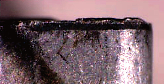
- Increase cutting speed.
- Use a sharp, PVD-coated grade, or another more suitable coated carbide grade.
- Select an insert with a more positive geometry.
- Improve coolant pressure.
What Is Chipping?
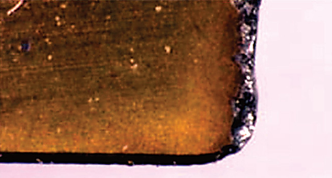
- Shock from an interrupted cut
- Vibration
- Hard scale or inclusions in the material
- A weak edge prep
- A cutting edge that is too brittle
- A built-up edge that has formed
- Select a tougher carbide grade.
- Use a stronger T-land or hone, or another insert with a stronger cutting edge.
- Ramp or roll into the cut, and reduce feed at the start of the cut.
- Check rigidity and improve the stability of the setup.
- Increase cutting speed.
- Select a positive geometry.
What Are Thermal (Comb) Cracks?
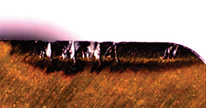
- Select a tougher insert grade.
- Run dry if practical. If you use coolant, keep the flow steady.
- Lower the cutting speed.
What Is Plastic Deformation?
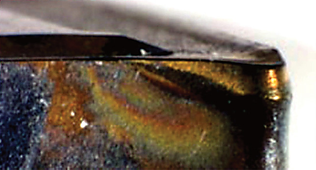
- Lower speed and feed.
- Select a harder, more wear-resistant grade with better hot hardness.
- Use a larger nose radius.
- Use a strong T-land.
What Is Notch Wear (DOC Line Wear)?
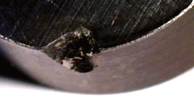
- Vary the depth of cut each pass.
- Increase the lead angle.
- Use an oxidation-resistant grade, or a more wear-resistant grade.
- Ramp into the cut.
- For work hardening materials, select a smaller entry angle.
- Reduce cutting speed on heat-resistant materials.
What Is Edge Fracture?
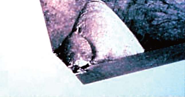
- Shock load
- Chatter
- Chip jamming
- A hard inclusion in the material
- A grade that is too brittle
- Too much wear before the insert was indexed
- A grade and geometry too weak for the job
- Too much load on the insert
- A built-up edge that has formed
- Select a tougher grade.
- Use a stronger edge prep, or a stronger, thicker insert.
- Reduce feed and depth of cut.
- Improve chip evacuation.
- Secure the fixturing.
Frequently Asked Questions
Which type of insert wear is normal?
Flank wear. It is the preferred type of wear and shows normal wear over time. If it happens fast, it can hurt surface finish and make tolerances vary.
What causes poor surface finish?
Six of the eight failure modes can cause it: fast flank wear, crater wear, built-up edge, thermal cracks, plastic deformation, and notch wear.
Which failure modes come from too much heat?
Crater wear comes from high temperatures and pressure on top of the insert. Plastic deformation comes from a cutting temperature that is too high. Thermal cracks come from big swings in temperature.
What causes built-up edge?
A cutting zone that is too cool. It is most common on gummy materials like low-carbon steel, 300-series stainless steel, and aluminum. Raising the cutting speed is the first fix.
Which failure mode can damage the cutter body or workpiece?
Edge fracture. A large break at the cutting edge can destroy the cutter body, the workpiece, or both.